
Transformer banks
3 posters
Page 1 of 1

Transformer banks
![]() topgroove Tue Jan 31, 2012 8:37 pm
topgroove Tue Jan 31, 2012 8:37 pm
Since three-phase is used so often for power distribution systems, it makes sense that we would need three-phase transformers to be able to step voltages up or down. This is only partially true, as regular single-phase transformers can be ganged together to transform power between two three-phase systems in a variety of configurations, eliminating the requirement for a special three-phase transformer. However, special three-phase transformers are built for those tasks, and are able to perform with less material requirement, less size, and less weight than their modular counterparts.
A three-phase transformer is made of three sets of primary and secondary windings, each set wound around one leg of an iron core assembly. Essentially it looks like three single-phase transformers sharing a joined core as in Figure below.
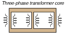
Three phase transformer core has three sets of windings.
Those sets of primary and secondary windings will be connected in either Δ or Y configurations to form a complete unit. The various combinations of ways that these windings can be connected together in will be the focus of this section.
Whether the winding sets share a common core assembly or each winding pair is a separate transformer, the winding connection options are the same:
•Primary - Secondary
• Y - Y
• Y - Δ
• Δ - Y
• Δ - Δ
The reasons for choosing a Y or Δ configuration for transformer winding connections are the same as for any other three-phase application: Y connections provide the opportunity for multiple voltages, while Δ connections enjoy a higher level of reliability (if one winding fails open, the other two can still maintain full line voltages to the load).
Probably the most important aspect of connecting three sets of primary and secondary windings together to form a three-phase transformer bank is paying attention to proper winding phasing (the dots used to denote “polarity” of windings). Remember the proper phase relationships between the phase windings of Δ and Y: (Figure below)

(Y) The center point of the “Y” must tie either all the “-” or all the “+” winding points together. (Δ) The winding polarities must stack together in a complementary manner ( + to -).
Getting this phasing correct when the windings aren't shown in regular Y or Δ configuration can be tricky. Let me illustrate, starting with Figure below.

Inputs A1, A2, A3 may be wired either “Δ” or “Y”, as may outputs B1, B2, B3.
Three individual transformers are to be connected together to transform power from one three-phase system to another. First, I'll show the wiring connections for a Y-Y configuration: Figure below

Phase wiring for “Y-Y” transformer.
Note in Figure above how all the winding ends marked with dots are connected to their respective phases A, B, and C, while the non-dot ends are connected together to form the centers of each “Y”. Having both primary and secondary winding sets connected in “Y” formations allows for the use of neutral conductors (N1 and N2) in each power system.
Now, we'll take a look at a Y-Δ configuration: (Figure below)

Phase wiring for “Y-Δ” transformer.
Note how the secondary windings (bottom set, Figure above) are connected in a chain, the “dot” side of one winding connected to the “non-dot” side of the next, forming the Δ loop. At every connection point between pairs of windings, a connection is made to a line of the second power system (A, B, and C).
Now, let's examine a Δ-Y system in Figure below.

Phase wiring for “Δ-Y” transformer.
Such a configuration (Figure above) would allow for the provision of multiple voltages (line-to-line or line-to-neutral) in the second power system, from a source power system having no neutral.
And finally, we turn to the Δ-Δ configuration: (Figure below)

Phase wiring for “Δ-Δ” transformer.
When there is no need for a neutral conductor in the secondary power system, Δ-Δ connection schemes (Figure above) are preferred because of the inherent reliability of the Δ configuration.
Considering that a Δ configuration can operate satisfactorily missing one winding, some power system designers choose to create a three-phase transformer bank with only two transformers, representing a Δ-Δ configuration with a missing winding in both the primary and secondary sides: (Figure below)

V” or “open-Δ” provides 2-φ power with only two transformers.
This configuration is called “V” or “Open-Δ.” Of course, each of the two transformers have to be oversized to handle the same amount of power as three in a standard Δ configuration, but the overall size, weight, and cost advantages are often worth it. Bear in mind, however, that with one winding set missing from the Δ shape, this system no longer provides the fault tolerance of a normal Δ-Δ system. If one of the two transformers were to fail, the load voltage and current would definitely be affected.
A three-phase transformer is made of three sets of primary and secondary windings, each set wound around one leg of an iron core assembly. Essentially it looks like three single-phase transformers sharing a joined core as in Figure below.
Three phase transformer core has three sets of windings.
Those sets of primary and secondary windings will be connected in either Δ or Y configurations to form a complete unit. The various combinations of ways that these windings can be connected together in will be the focus of this section.
Whether the winding sets share a common core assembly or each winding pair is a separate transformer, the winding connection options are the same:
•Primary - Secondary
• Y - Y
• Y - Δ
• Δ - Y
• Δ - Δ
The reasons for choosing a Y or Δ configuration for transformer winding connections are the same as for any other three-phase application: Y connections provide the opportunity for multiple voltages, while Δ connections enjoy a higher level of reliability (if one winding fails open, the other two can still maintain full line voltages to the load).
Probably the most important aspect of connecting three sets of primary and secondary windings together to form a three-phase transformer bank is paying attention to proper winding phasing (the dots used to denote “polarity” of windings). Remember the proper phase relationships between the phase windings of Δ and Y: (Figure below)
(Y) The center point of the “Y” must tie either all the “-” or all the “+” winding points together. (Δ) The winding polarities must stack together in a complementary manner ( + to -).
Getting this phasing correct when the windings aren't shown in regular Y or Δ configuration can be tricky. Let me illustrate, starting with Figure below.
Inputs A1, A2, A3 may be wired either “Δ” or “Y”, as may outputs B1, B2, B3.
Three individual transformers are to be connected together to transform power from one three-phase system to another. First, I'll show the wiring connections for a Y-Y configuration: Figure below
Phase wiring for “Y-Y” transformer.
Note in Figure above how all the winding ends marked with dots are connected to their respective phases A, B, and C, while the non-dot ends are connected together to form the centers of each “Y”. Having both primary and secondary winding sets connected in “Y” formations allows for the use of neutral conductors (N1 and N2) in each power system.
Now, we'll take a look at a Y-Δ configuration: (Figure below)
Phase wiring for “Y-Δ” transformer.
Note how the secondary windings (bottom set, Figure above) are connected in a chain, the “dot” side of one winding connected to the “non-dot” side of the next, forming the Δ loop. At every connection point between pairs of windings, a connection is made to a line of the second power system (A, B, and C).
Now, let's examine a Δ-Y system in Figure below.
Phase wiring for “Δ-Y” transformer.
Such a configuration (Figure above) would allow for the provision of multiple voltages (line-to-line or line-to-neutral) in the second power system, from a source power system having no neutral.
And finally, we turn to the Δ-Δ configuration: (Figure below)
Phase wiring for “Δ-Δ” transformer.
When there is no need for a neutral conductor in the secondary power system, Δ-Δ connection schemes (Figure above) are preferred because of the inherent reliability of the Δ configuration.
Considering that a Δ configuration can operate satisfactorily missing one winding, some power system designers choose to create a three-phase transformer bank with only two transformers, representing a Δ-Δ configuration with a missing winding in both the primary and secondary sides: (Figure below)
V” or “open-Δ” provides 2-φ power with only two transformers.
This configuration is called “V” or “Open-Δ.” Of course, each of the two transformers have to be oversized to handle the same amount of power as three in a standard Δ configuration, but the overall size, weight, and cost advantages are often worth it. Bear in mind, however, that with one winding set missing from the Δ shape, this system no longer provides the fault tolerance of a normal Δ-Δ system. If one of the two transformers were to fail, the load voltage and current would definitely be affected.

topgroove- Posts : 428
Join date : 2012-01-29
Re: Transformer banks
![]() BATTMAN Wed Feb 01, 2012 12:34 pm
BATTMAN Wed Feb 01, 2012 12:34 pm
Nice first post in Electrical Theory. Groove has a good start with good people here. The Old BATTMAN is on a fixed retirement income, but will drop a buck or two on him at different times to make sure it gets off the ground and become THE LINEMAN'S FORUM.

BATTMAN- Posts : 75
Join date : 2012-02-01
Age : 78
Location : Edna,KS and Wichita Falls, TX -

Thanks!
![]() BC_boy Wed Feb 01, 2012 5:45 pm
BC_boy Wed Feb 01, 2012 5:45 pm
This stuff is great, took reading it a few times over a few days for it to sink in but that's what they call learning.
What does this mean though? (the 2 and the symbol)
V” or “open-Δ” provides 2-φ power with only two transformers.
What does this mean though? (the 2 and the symbol)
V” or “open-Δ” provides 2-φ power with only two transformers.

BC_boy- Posts : 50
Join date : 2012-01-30
Age : 35
Location : Kanata
Re: Transformer banks
![]() topgroove Wed Feb 01, 2012 6:05 pm
topgroove Wed Feb 01, 2012 6:05 pm
That had me scratching my head too... Thats engineer talk for two legs of a delta forming the third leg. The vector looks like a triangle thats missing one side.
topgroove- Posts : 428
Join date : 2012-01-29
2 - and the symbol...
![]() dubldaz Sun Jul 06, 2014 6:38 pm
dubldaz Sun Jul 06, 2014 6:38 pm
I think it means 2-phase(as in 2 phases vs. 3)
dubldaz- Guest
» Capacitor locations
» A great tutorial on capacitor banks
» transformer question
» Polarity of tranformers
» ever wonder how a distribution transformer is manufactured.
» A great tutorial on capacitor banks
» transformer question
» Polarity of tranformers
» ever wonder how a distribution transformer is manufactured.
Page 1 of 1
Permissions in this forum:
You cannot reply to topics in this forum